In HVAC systems, duct tees, crosses, and reducers are common components used to regulate and distribute airflow. Below are their general applications:
Duct T-shaped fitting (T-shaped duct): A duct T-shaped fitting is used to split airflow into two directions, commonly employed in branch airflow systems. During installation, a T-shaped fitting is typically used to connect three ducts. One duct serves as the inlet, while the other two ducts function as branch outlets. This configuration allows airflow to be distributed from a main duct to two branch ducts, meeting the air supply requirements of different areas.
Duct four-way (cross-type duct): Duct four-way fittings are used to divide airflow into three directions and are commonly used in complex airflow systems. They have one inlet and three outlets. During installation, a four-way fitting is typically used to connect four ducts. The inlet is connected to the main duct, while the outlets are connected to the three branch ducts requiring air supply. This configuration allows airflow to be distributed to different areas, enabling more precise air supply control.
Duct diameter changes: In certain situations, it is necessary to make radial changes in the duct system to accommodate different layouts and space constraints. Duct diameter changes are typically achieved using transition sections or reducing/expanding methods. A transition section is a gradually changing duct connector used to connect two ducts of different diameters. Reducing/expanding involves changing the diameter of a section of duct by either reducing or expanding it.
When installing three-way, four-way, or diameter-changing ducts, it is essential to ensure the sealing and flow characteristics of the connection points to prevent air leaks or airflow losses. Additionally, proper sizing and airflow velocity calculations must be performed based on the system design requirements and HVAC load.
Please note that the specific design and installation methods for duct systems may vary depending on the system type, scale, and specific requirements. Therefore, it is advisable to consult professional HVAC engineers or suppliers in actual projects to ensure proper design and installation implementation.
Detailed Guide to the Manufacturing Process of Duct Accessories: Key Points for the Production of Reducers, Tees, and Branch Pipes
Key Steps and Precautions for the Manufacturing and Installation of Duct Tees and Crosses
Duct tees and crosses are crucial components of ventilation systems, and their manufacturing and installation quality directly impacts the overall system performance. This article aims to provide a comprehensive guide to help readers understand the key steps in the manufacturing and installation of duct tees and crosses, ensuring the smooth operation of ventilation systems. We will now delve into the manufacturing and installation process of duct tees and crosses, offering practical operational recommendations for readers.
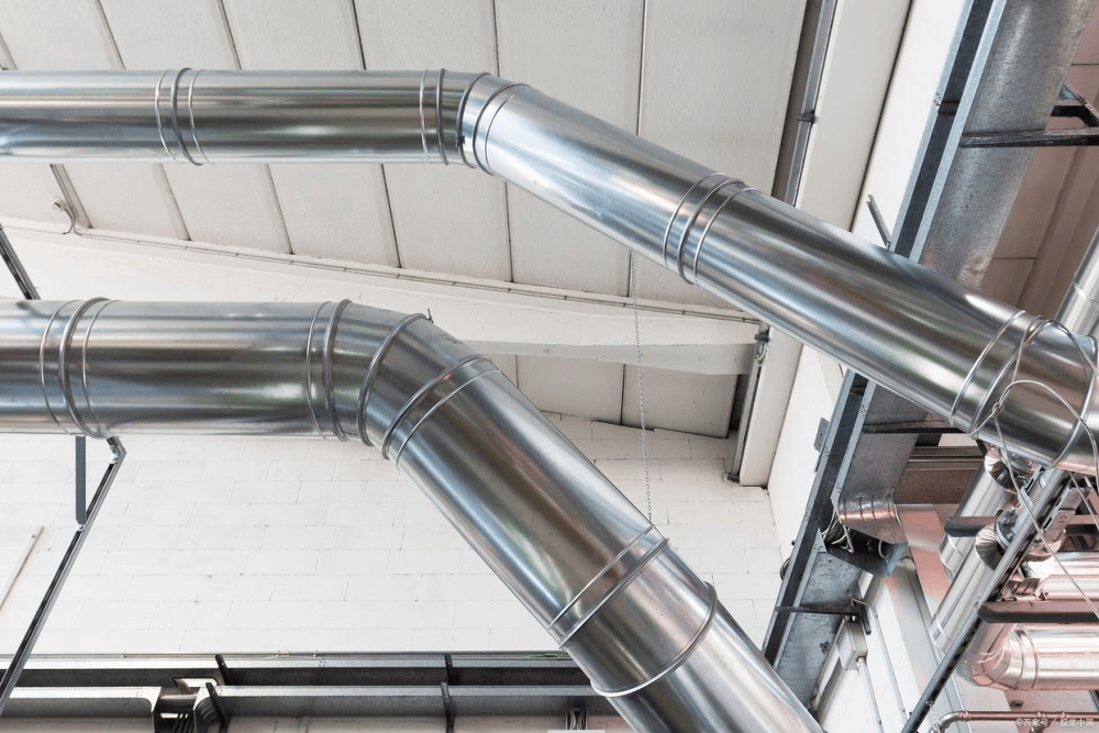
3-way and 4-way air duct installation guide
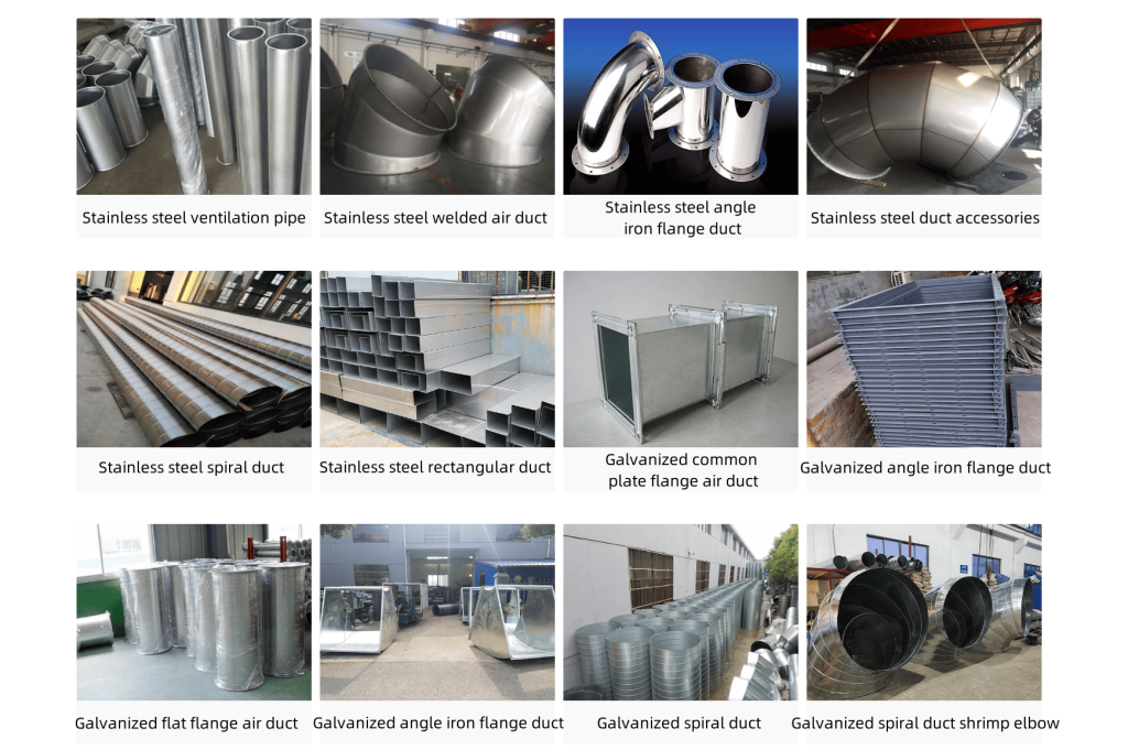
◆ Scope of Application and Physical Diagram Display
This guide applies to the manufacturing process of duct tees and crosses in ventilation, air conditioning, and smoke exhaust systems made of various materials. Next, we will use physical diagrams to detail the manufacturing process and key steps for duct tees and crosses.
◆ Detailed Construction Drawing Analysis
Next, we will use detailed construction drawings to reveal every step and critical phase of the fabrication process for ductwork tees and crosses. These drawings will clearly illustrate each step and critical phase of the fabrication process, helping you gain a deeper understanding of the process.
◆ Core Processes and Construction Requirements
A standardized construction process is critical for reducing local resistance and noise. When fabricating duct tees and crosses, ensure that the joints at the branch points are tightly sealed. If any cracks are detected, immediately fill them with sealant for repair. Additionally, adjust the height of the branch pipes according to on-site conditions, using either a bottom-level or top-level approach for gradual diameter transitions, and strictly adhere to the manufacturing process requirements for duct diameter transition pipes. Furthermore, if the side length of a branch duct along the main airflow direction is less than that of the main duct, the branch opening of the branch duct should be designed as a variable-diameter form.
At the connection point between branch ducts and the main duct, concentric arc-shaped bends with a curvature radius equal to one side length of the plane are typically used to ensure smooth airflow transition. When the duct length is ≥500mm, deflector blades must be added, made from galvanized iron sheet with a thickness of δ≥0.75mm. The arc length of the deflector blades should match the inner arc length of the bend and be designed as a concentric circle.
If the height is greater than or equal to 1250 mm, reinforcement measures should be taken, and galvanized rivets should be used for fixation. The inner arc of the deflector blades should be concentric with the bent pipe, and the design should ensure smooth connection with the inner arc of the duct. The spacing L between the deflector blades can be set using equal intervals or a gradual gradient, but note that the maximum distance between the deflector blades and the inner/outer arcs, as well as the maximum blade spacing, should not exceed 500mm. Additionally, the minimum blade spacing should not be less than 200mm. When determining the number of deflector blades, you can use the method of dividing the plane side length by multiples of 500, but the maximum number should not exceed 4 blades. Furthermore, the guide vanes must be securely fixed to the ductwork using bolts or rivets.
Notes: When connecting the side branches of three-way or four-way fittings to the main duct, a lap joint connection method should be used to avoid direct riveting to the main duct, ensuring the standardization of the connection and the smooth flow of air.
When fabricating square-to-round transition ducts, direct installation of round ducts onto square boxes should be avoided to minimize local resistance and noise generation.
Y-type three-way and four-way elbow galvanized pipe white iron sheet ventilation duct fittings processing
White iron sheet stainless steel duct processing Galvanized pipe Ventilation duct fittings Y-type Three-way Four-way Elbow
Y-type Three-way Four-way Elbow Galvanized pipe white iron sheet ventilation duct fittings processing
Three-way and four-way valves: Critical components in piping systems
Three-way and four-way valves are indispensable components in piping systems, primarily serving to alter the flow direction of the medium and facilitate branching or convergence within the piping system. The following provides a basic overview of these two types of fittings:
Three-way valve
A three-way valve features three open ports and is primarily categorized into two forms: T-type and Y-type.
T-type three-way valve (Tee): One inlet port and two outlet ports, allowing the medium to enter through the inlet and exit through two separate outlets.
Y-type three-way valve (Y-branch): Also has one inlet port and two outlet ports, but its shape resembles the letter “Y,” with the medium splitting evenly between the two outlet ports from the inlet.
Four-way valve
A four-way valve, also known as a cross joint or Cross, has four ports, each of which can serve as an inlet or outlet, enabling connections or diversions in four directions within a pipeline system.
In pipeline systems, four-way valves are primarily used at pipeline intersections to allow the medium to flow in from one direction and branch out to three other directions, or to converge from three directions and flow toward another direction.
Material Selection
The manufacturing materials for three-way and four-way valves can be metal (such as carbon steel, stainless steel, cast iron, etc.), plastic (such as PVC, PE, etc.), or other composite materials, with the specific choice depending on the actual application environment and the characteristics of the conveyed medium.
Application Areas
Three-way and four-way valves are widely used in pipeline systems across various industries such as building plumbing, petrochemicals, metallurgy, and power generation, serving as an indispensable component of pipeline systems.
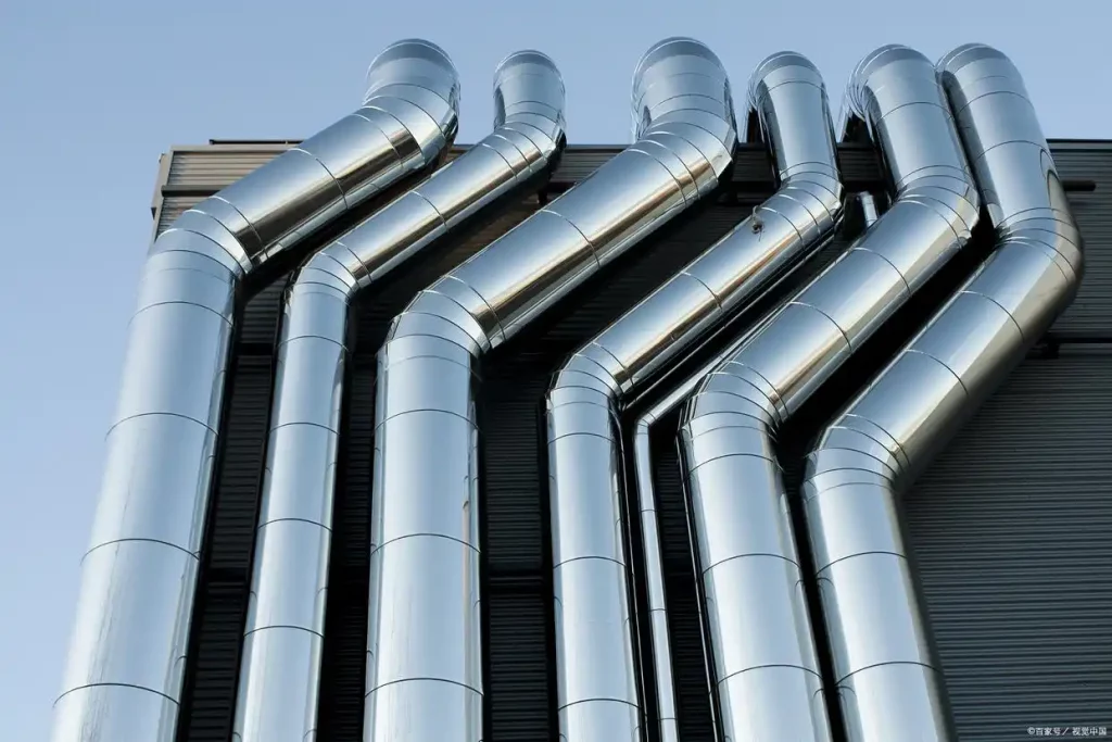
Features of spiral ductwork:
Since sheet metal is prone to chemical reactions in various environments, leading to corrosion and rusting, zinc remains virtually unchanged in dry air. In humid conditions, the zinc surface forms a dense layer of basic zinc carbonate. Spiral ducts primarily involve applying a zinc coating to the sheet metal of the duct, providing protection for the sheet metal. After undergoing passivation treatment, dyeing, or coating with a protective agent, the zinc coating significantly enhances both its protective and decorative properties.
Spiral ducts have the following features:
1. Smooth appearance, free of zinc nodules or burrs, with a silver-white color;
2. Easy to install with fewer connection points;
3. Low airflow resistance and minimal ventilation noise;
4. Good strength and rigidity;
5. Controllable thickness, with options ranging from 5 to 107 μm;
6. No hydrogen embrittlement or temperature-related hazards, with unchanged material mechanical properties;
7. Can replace certain processes that require hot-dip galvanizing;
8. Excellent corrosion resistance, with neutral salt spray test results reaching 240 hours;
9. Manufactured using hot-dip galvanizing, suitable for highly corrosive environments such as strong acid or alkali fumes;
10. Custom design and fabrication of ducts to meet specific customer requirements.
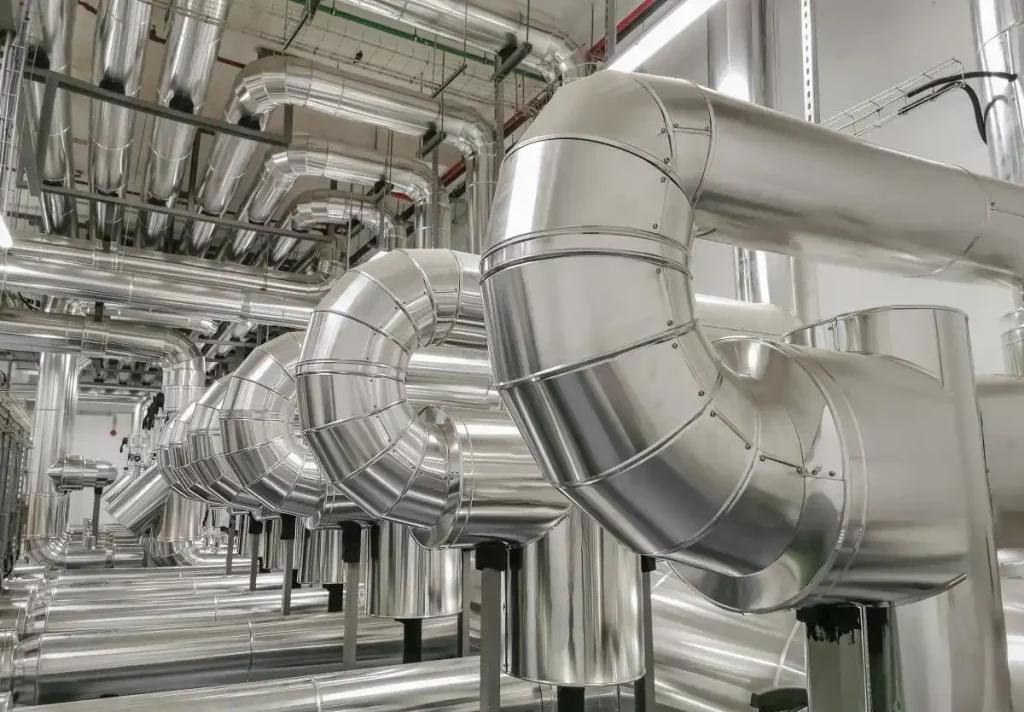
Compared to traditionally hand-hammered white iron pipes, mechanically manufactured spiral ducts offer the following advantages:
(1) Excellent sealing performance.
(2) High strength and rigidity.
(3) Low ventilation resistance and low ventilation noise, with round ducts outperforming square ducts.
(4) Easy installation with fewer connection points.
(5) High-quality appearance and aesthetic appeal.