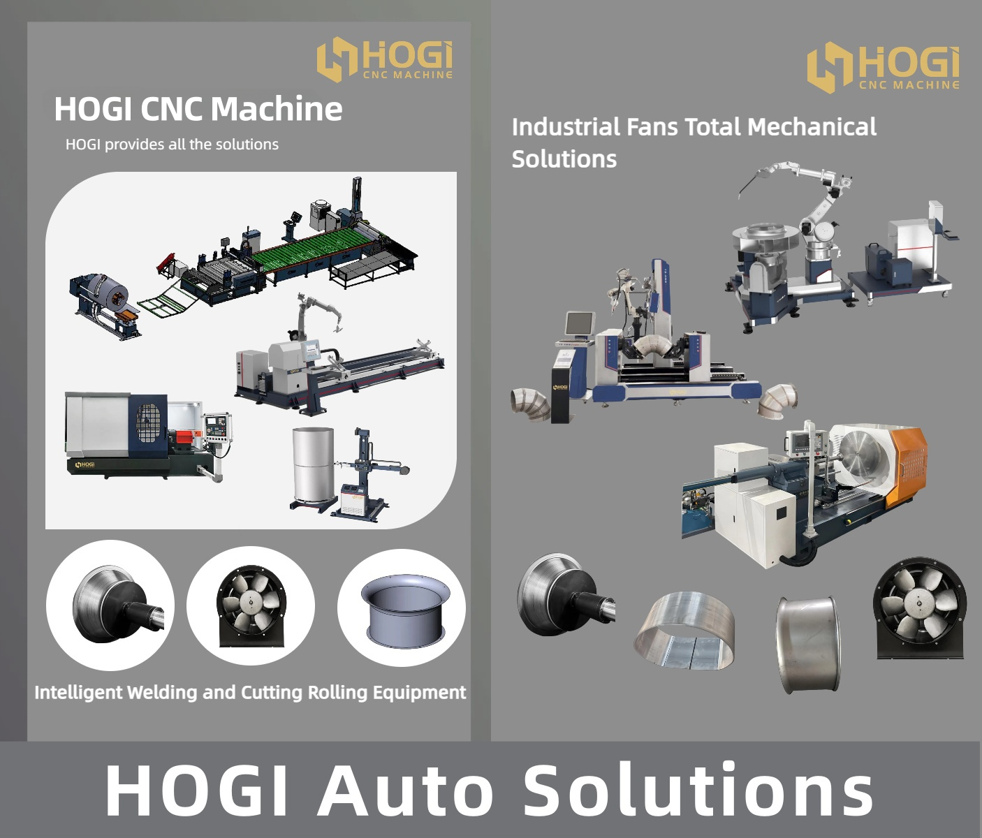
Stainless steel storage tanks are widely used in numerous industries such as chemical, food, and pharmaceutical due to their excellent corrosion resistance, high strength, and hygienic properties. Their manufacturing process involves various process components as well as precise welding and machining techniques. Below is a detailed introduction to the entire production process of stainless steel storage tanks.
I. Raw Material Preparation Stainless steel tanks typically utilize stainless steel plates such as grades 304 and 316L, which offer excellent corrosion resistance and workability. Based on the tank’s design specifications, the required plate dimensions and quantities are precisely calculated.
(1) Cutting Process.
Laser Cutting Machine: Laser cutting technology is widely applied in stainless steel sheet processing. It employs a high-energy-density laser beam to irradiate the sheet, causing the material to instantly melt or vaporize, thereby achieving the cutting objective. For thinner stainless steel sheets (generally below 8mm), laser cutting machines can achieve high-precision cutting with smooth edges and minimal heat-affected zones. For instance, when cutting circular plates for tank heads, laser cutting machines precisely control the cutting path, ensuring dimensional accuracy with tolerances within ±0.1mm..
Plasma Cutting: Plasma cutting machines are more suitable for stainless steel plates exceeding 8mm in thickness. They cut by melting the plate with a high-temperature plasma arc and blowing away the molten material. Plasma cutting offers high speed and efficiency for thicker plates, though the cut edges are rougher than laser cuts and the heat-affected zone is slightly larger. When cutting large-scale tank side plates, plasma cutters rapidly complete extensive cutting tasks, meeting production efficiency demands.
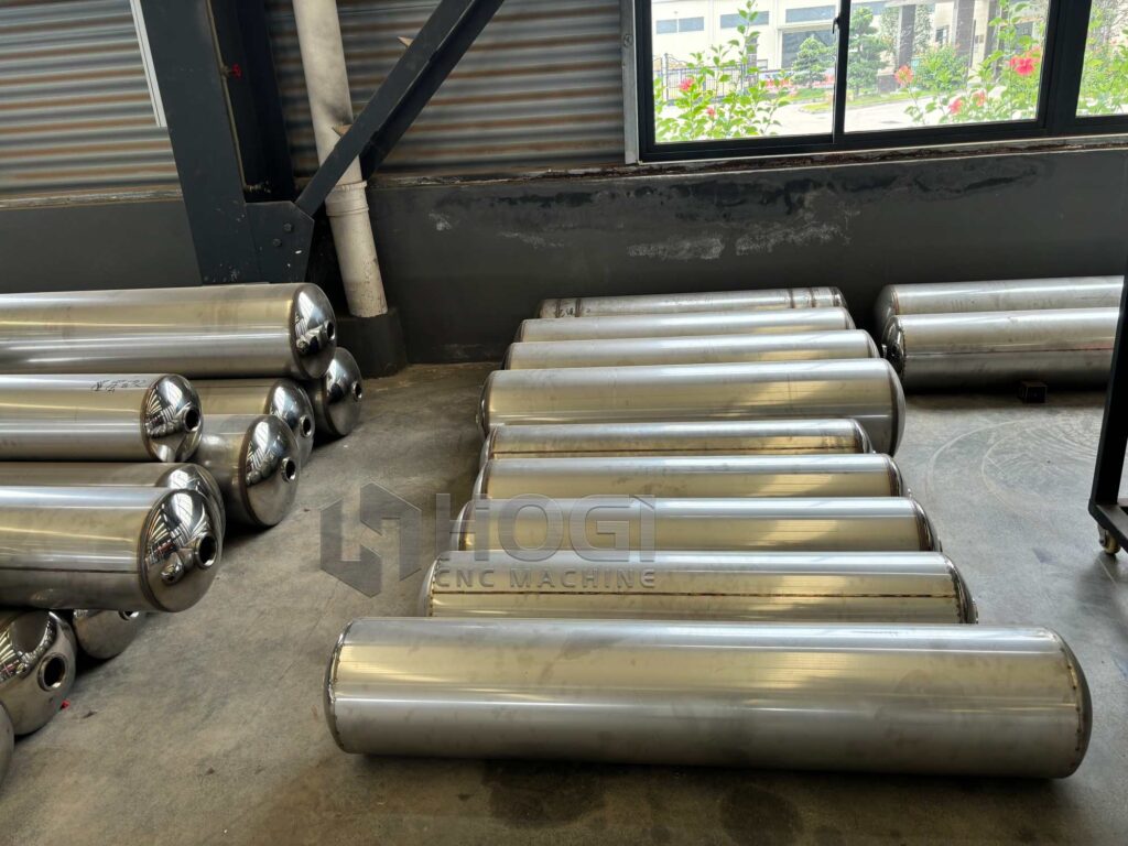
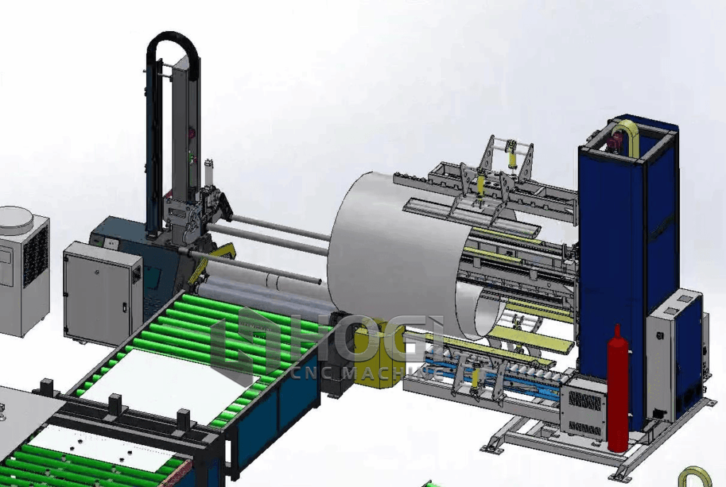
II. Tank Body Forming Process
(1) Plate Rolling Process
Cut stainless steel plates undergo rolling to form the cylindrical section of the tank body. A plate rolling machine progressively bends the plates, with strict control over plate curvature during rolling to ensure the circumference and diameter of the rolled cylinder meet design specifications. Typically, specific parameters are set on the rolling machine, supplemented by manual measurement and adjustment, to control the cylinder’s ovality within a minimal range. The ovality error is generally kept within ±2mm to ensure the stability of subsequent welding and the overall structure.
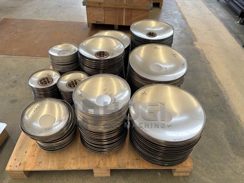
(2) Head Fabrication Process
Stamping Forming: Tank heads are typically produced using stamping forming. Cut circular stainless steel plates are placed into stamping dies, where immense pressure from a press deforms the plate into the required head shape within the die. Stamped heads feature smooth surfaces and regular shapes, ensuring excellent pressure-bearing performance. For standard elliptical heads, dimensional accuracy between the major and minor axes can be controlled within ±1mm.
Spinning Forming: For large or non-standard heads, spinning offers an alternative manufacturing method. Spinning equipment rotates the sheet while applying pressure through rollers, progressively deforming it into the head shape. This process enables production of thicker, larger heads and allows real-time adjustments to shape and dimensions during fabrication, ensuring consistent quality.
III. Process Fittings Introduction and Welding Methods
(1) Pipe Connections
Fitting Description: Pipe connections link the storage tank to external pipelines, including feed pipes, discharge pipes, and drain pipes. They share the same material as the tank body, with specifications determined by operational requirements.
Welding Methods: Pipe connections to the tank body typically employ a combination of manual metal arc welding (MMAW) and gas tungsten arc welding (GTAW). MMAW is first used for root pass welding to ensure root strength, followed by GTAW for the cover pass to achieve an aesthetically pleasing weld appearance and corrosion resistance. During welding, precise control of welding current, voltage, and welding speed is essential to guarantee weld quality. For example, for a 100mm diameter nozzle, the welding current for MIG root pass is controlled at 100–120A, while the TIG cover pass current is set at 80–100A. Upon completion, all welds undergo 100% radiographic inspection to verify the absence of internal defects.
(II) Manhole
Accessory Description: Manholes are installed to facilitate personnel entry into the tank interior for maintenance, cleaning, and other operations. Manholes adhere to standard specifications, typically employing necked butt-weld flange manholes or swing-cover necked butt-weld flange manholes, constructed from stainless steel.
Welding Method: The welding of manholes to the tank body employs a combined process of manual arc welding and argon arc welding. Prior to welding, precise positioning and assembly of the connection between the manhole and tank body must be performed to ensure uniform gaps. During welding, manual arc welding is first used for the root pass, followed by multiple layers and passes of argon arc welding to guarantee weld strength and sealing integrity. After welding, the manhole welds undergo penetrant testing to detect micro-cracks and other defects, ensuring operational safety.
(3) Level Gauge Interface
Component Description: The level gauge interface is used to install liquid level measurement devices for real-time monitoring of tank contents. Available in various configurations such as flanged or threaded types, it is constructed from stainless steel.
Welding Method: TIG welding is typically employed for level gauge interfaces. Given their relatively small dimensions and stringent quality requirements, TIG welding enables precise control to guarantee weld quality and aesthetics. During welding, heat input must be carefully managed to prevent deformation from overheating, which could compromise gauge installation and functionality. After welding, conduct a visual inspection of the weld to ensure it is free of defects such as porosity or cracks.
(IV) Reinforcement Ring
Accessory Description: The reinforcement ring enhances the strength and stability of the tank shell, preventing deformation under operational stresses. Typically fabricated from flat steel or angle steel, its material matches that of the tank body.
Welding Method: Intermittent welding is employed to join the reinforcement ring to the tank shell. Position the ring on the shell according to design specifications, then weld intermittently at intervals (typically 200–300 mm). Weld length varies based on ring specifications and stress conditions, generally ranging from 50–100 mm. This approach ensures the connection strength between the reinforcement ring and the tank body while minimizing the impact of welding deformation on the tank body. During welding, pay attention to the welding sequence and perform symmetrical welding to balance welding stresses.
(5) Fishscale Pattern Effect on Welds
In stainless steel storage tank fabrication with stringent aesthetic requirements, achieving a fishscale pattern on welds is often desired. This effect is primarily realized through TIG welding techniques. By controlling the oscillation amplitude, speed, and welding current during TIG welding, the molten weld metal forms regular fishscale-like patterns as it solidifies. Specifically, the torch oscillates at a controlled angle and frequency—typically 30° to 45° with 2 to 3 oscillations per second—while adjusting the welding current according to the weld’s width and depth. This technique yields welds with an aesthetically pleasing fish scale appearance while ensuring internal integrity, delivering excellent strength and corrosion resistance.
IV. Overall Welding and Quality Inspection
(A) Overall Welding Process
After completing the installation and welding of all process components, proceed with the overall welding of the tank body. Perform butt welding between the rolled cylinder and the head, primarily using submerged arc welding. Submerged arc welding offers advantages such as high welding efficiency and stable weld quality, enabling the completion of long welds within a short timeframe. During welding, parameters such as welding current, voltage, welding speed, and welding angle must be strictly controlled. For example, for a 10mm-thick plate butt weld, the submerged arc welding current is controlled between 500–600A, voltage between 30–32V, and welding speed at 30–40cm/min. Simultaneously, real-time monitoring of the welding process is essential to ensure weld quality.
(II) Quality Inspection.
Visual Inspection: Conduct a comprehensive visual examination of the completed tank. Inspect the weld surface for flatness, smoothness, and the absence of defects such as porosity, cracks, or undercut. Weld bead height and misalignment must comply with relevant standards. Typically, weld bead height is controlled between 0–3 mm, and misalignment does not exceed 10% of plate thickness or 1.5 mm..
Non-Destructive Testing: Internal weld quality is assessed using non-destructive testing methods such as radiographic testing, ultrasonic testing, and penetrant testing. Radiographic testing detects internal defects like porosity, slag inclusions, and cracks. Critical welds require 100% radiographic inspection following industry-specific standards. Ultrasonic testing complements radiography by identifying area-type internal defects. Penetrant testing primarily detects surface microcracks and open defects to ensure tank integrity.
Pressure Testing: After completing all welding and inspection work, the storage tank undergoes pressure testing. Based on the tank’s design pressure, it is filled with gas or liquid at a specified pressure, typically using a hydrostatic test. During testing, pressure is gradually increased to 1.25 times the design pressure and maintained for a set duration (usually 30 minutes). The tank body and welds are then inspected for leaks, deformation, or other abnormalities. Only after passing the pressure test is the storage tank considered complete and ready for service.
The manufacturing process of stainless steel storage tanks involves multiple stages and diverse technologies. From raw material cutting and tank forming to the installation and welding of process components, followed by final quality inspection, each step requires strict control to ensure the tank’s quality and performance meet practical operational requirements.